Shale Sampling: Coring, Transport, Finishing
It is difficult to overstate the importance of studying cores in the context of petroleum engineering. Cores are critical for quickly learning the key components of a reservoir. Reservoir models used by petroleum engineers rely on accurate porosity, permeability and mineralogy for characterization. Cores also relate hydrocarbon production to reservoir models. Toward this end, cores provide engineers with the actual reservoir texture – the rock matrix, natural fractures and any hydrocarbon staining present.
Given core’s importance, the steps I took for coring, transporting and finishing samples are listed below and then described in detail.
Steps taken:
- Viable rock fragment selections made
- Cores drilled (parallel and perpendicular to bedding plane, and oriented to North)
- Samples labeled and packed for transport
- Protective cover devised for shale samples in bandsaw vise
- Samples trimmed to size with bandsaw
- Samples finished for testing by grinding smooth and square
With the exception of samples from the oriented Oatka Creek rock fragment, testing samples came from Marcellus Shale outcrop in Bedford, Pennsylvania. Outcrop fragments to be cored were chosen for their matrix competence and a minimum thickness of 2 ½ inches.
Samples were cored using a drill press, a one inch coring bit, and tap water via a peristaltic pump to keep the bit cool and the shale from cracking. Coring was completed in the rock lab in Morgantown, West Virginia at the National Energy Technology Laboratory.
A note on diamond coring bits, bandsaw blades and grinding wheels: shale by nature does not withstand aggressive kerfs typically used on stronger, more competent rock, nor does shale withstand much compressive force. Diamond tipped bits, blades and wheels have the advantage of high efficiency and low force, an ideal combination for prepping shale specimens. For all aspects (coring, sizing, and grinding) diamond bits, blades and wheels were used on the shale.

Figure 1: Drill press with peristaltic water pump and 1″ coring bit
Core samples were drilled perpendicular and parallel to bedding planes in Marcellus Shale. Cores oriented to North came from the Oatka Creek member of the Marcellus Shale (Figure 2 and Figure 3).
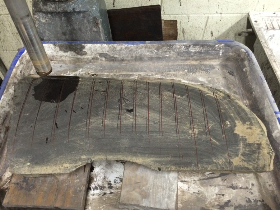
Figure 2: Oatka Creek member of Marcellus shale fragment showing North arrow and corresponding black and red lines to keep core samples oriented
As will be discussed further in future writing, the joint system described by Terry Engelder is particularly evident in the Oatka Creek member (Figure 3).
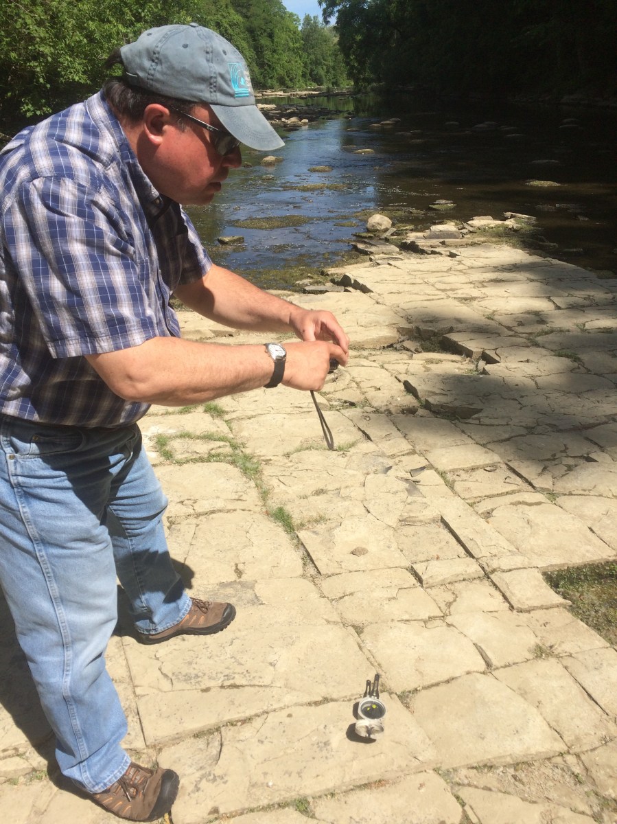
Figure 3: Mentor photographing joint pattern in the eponymously named Oatka Creek member at Oatka Creek
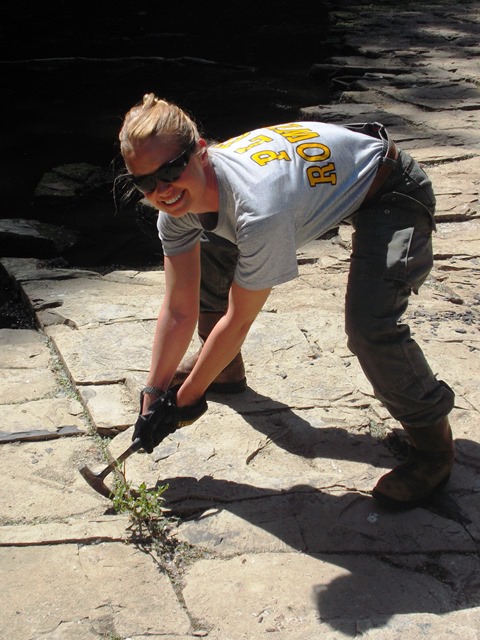
As for the Bedford, PA Marcellus shale samples, several cores showed evidence of natural gas evolving out of the rock (Figure 4) along the seam of a natural fracture. The smell of crude oil permeated the coring process and on rare occasion, H2S.
An oil film was also seen on the water in the drip pan of the drill press indicating the presence of hydrocarbons in the outcrop rock fragments.

Figure 4: Newly cored sample with natural gas bubbling out of natural fracture
Shales are fragile rock, which meant coring the rock fragments needed to be a slow, deliberate process (Figure 5 and Figure 6).
Despite great time and care taken with coring, several challenges arose while sampling the shale:
- cores broke partway through the coring process;
- cores ended up too short for testing as they would split along bedding planes and “poker chip”;
- occasionally shale fines created a thick enough mud that samples stuck in the core bit and required breaking to get out; and
- natural fractures not evident on the surface of the rock fragment split the core sample after it had been drilled.

Figure 5: Drill bit, coring bits (2″ and 1″ respectively), sample, and cored rock fragment for comparison
The decision for 1 inch diameter samples resulted from three considerations:
- One inch is a diameter that can be tested in most permeameters; using this diameter makes permeability testing in various machines an option;
- In compressive tests, the ratio of diameter to length is 1:2 which meant the rock fragment thickness would be less of an issue (compared to a 2 inch diameter sample needing 4 inches for the length requirement);
- The Marcellus, like most shales, has nano- to milli- darcy level permeability which means conducting permeability tests on smaller samples would decrease the amount of time needed to complete tests.

Figure 6: Example of post-coring rock fragments
The samples were then immediately placed in a plastic Ziploc bag and labeled with sample number, coring direction (parallel, perpendicular, or angle), and outcrop fragment designation, and transported via personal vehicle from Morgantown, West Virginia to Rapid City, South Dakota (Figure 7).
The core samples remained sealed in their bags and in protective bubble wrap in the box while I completed modifications to the GCTS.
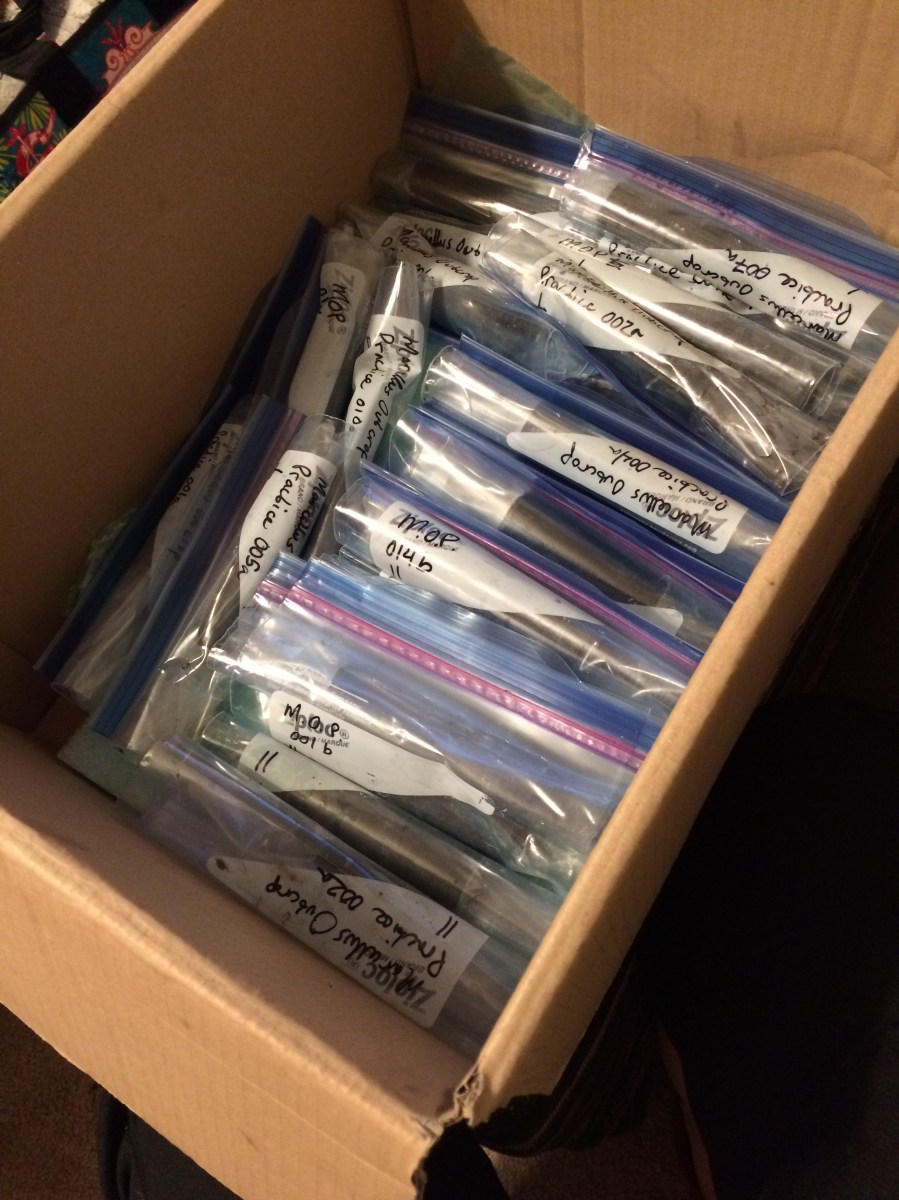
Figure 7: Box of labeled, zip-locked samples ready for transport
A horizontal bandsaw was used to trim the samples to length. Prior to trimming, a protective cover needed to be constructed to house the shale sample while it was in the bandsaw. The protective block gives the vise on the bandsaw something to grip on to without damaging the shale sample. I worked with Steve Olsberg at RESPEC in the Geomechanics Lab shop to complete the remainder of the work described below.
A 4 inch x 4 inch block of wood was cored out using a 1 inch Forstner bit. The cored block was then trimmed to 2 3/8” in length, and sliced in half (Figure 8 and Figure 9). Slicing the block in half made sandwiching the sample easier, rather than trying to slide the sample into the block and risking damage to the core.
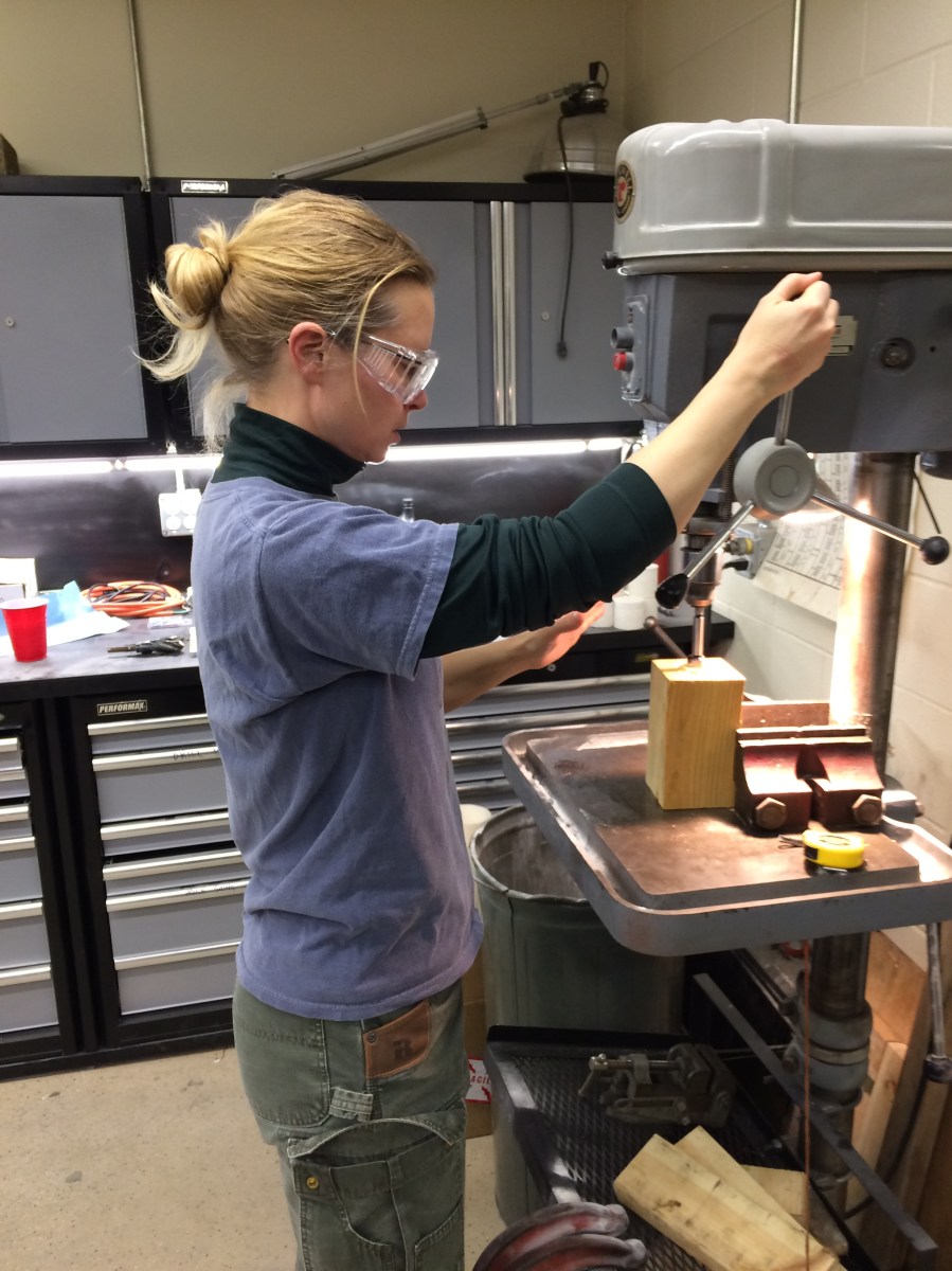
Figure 8: Coring out center of bandsaw block

Figure 9: Cored out 4″x4″ wood block for both protecting and stabilizing core in bandsaw
The blade on the bandsaw was changed to a medium grit, 60/80 diamond continuous blade which yields a much finer cut and is less destructive to the shale sample (Figure 10).
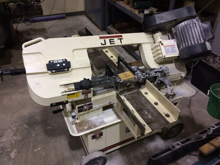
Figure 10: Horizontal Bandsaw with wood block and shale sample
Next, the shale samples were squared using a grinder to ensure an even distribution of axial compressive force and uniform distribution of saturating gas or liquid. Since the samples will not be used for compressive testing, it was not necessary to grind them to within 1/10,000th inch parallel.

Figure 11: Protective and stabilizing plastic sleeve for protecting shale during grinding
As with the bandsaw, a protective covering was used for the shale while the sample was in the grinder (Figure 11 and Figure 12). The plastic covering kept the sample stable and prevented compressive damage from the mechanical vise.

Figure 12: Diamond grinding stone used to smooth and square sample ends
Once the ends of the samples were ground smooth and square, they were put back into their respective bags with a “G” denoting the sample had been ground and was ready for testing.
Next Steps
- Transient permeability testing at MT Tech using gas;
- Finish GCTS modifications for poroelastic testing; and
- Conduct transient permeability test at SDSM&T using liquid.


Hello,
I hope this message finds everything well. Your work and specially your blog in sample preparations had been very helpful for me. I really appreciate you share your experience so others like me can have an idea about what to expect and how to solve those issues. I am wondering if it is possible for you to advice in some questions I have concerning the coring preparation. I know you might be really busy but hope you can help me. My e-mail is jjap84@outlook.com in case you can please let me know so I can replay with my concerns to have your advice then.
have a great night,
Jose Aramendiz
LikeLike